INTERNOLD NETWORKS CCNA LIVE WEBCLASS (INCLW)
Troubleshooting Ethernet LANs
Troubleshooting Ethernet LANs
This lesson focuses on the processes of verification and troubleshooting.
Verification refers to the process of confirming whether a network is working as designed.
Troubleshooting refers to the follow-on process that occurs when the network is not working as designed, by trying to determine the real reason why the network is not working correctly, so that it can be fixed.
Sometimes, when people take their first Cisco exam, they are surprised at the number of verification and troubleshooting questions. Each of these questions requires you to apply networking knowledge to unique problems, rather than just being ready to answer questions about lists of facts that you’ve memorized. You need to have skills beyond simply remembering a lot of facts.
This lesson discusses a wide number of topics.
- Analyzing switch interfaces and cabling
- Predicting where switches will forward frames
- Troubleshooting port security
- Analyzing VLANs and VLAN trunks
Perspectives on Applying Troubleshooting Methodologies
This first section of the lesson takes a brief diversion for one particular big idea: what troubleshooting processes could be used to resolve networking problems? Most CCNA Routing and Switching exam topics list the word “troubleshoot” along with some technology, mostly with some feature that you configure on a switch or router. One exam topic makes mention of the troubleshooting process. This first section examines the troubleshooting process as an end to itself.
The first important perspective on the troubleshooting process is this: you can troubleshoot using any process or method that you want. However, all good methods have the same characteristics that result in faster resolution of the problem, and a better chance of avoiding that same problem in the future.
The one exam topic that mentions troubleshooting methods uses some pretty common terminology found in troubleshooting methods both inside IT and in other industries as well.
The ideas make good common sense. From the exam topics:
- Step 1. Problem isolation and documentation: Problem isolation refers to the process of taking what you know about a possible issue, confirming that there is a problem, and determining which devices and cables could be part of the problem, and which ones are not part of the problem. This step also works best when the person troubleshooting the problem documents what they find, typically in a problem tracking system.
- Step 2. Resolve or escalate: Problem isolation should eventually uncover the root cause of the problem—that is, the cause which, if fixed, will resolve the problem. In short, resolving the problem means finding the root cause of the problem and fixing that problem. Of course, what do you do if you cannot find the root cause, or fix (resolve) that root cause once found? Escalate the problem. Most companies have a defined escalation process, with different levels of technical support and management support depending on whether the next step requires more technical expertise or management decision making.
- Step 3. Verify or monitor: You hear of a problem, you isolate the problem, document it, determine a possible root cause, and you try to resolve it. Now you need to verify that it really worked. In some cases, that may mean that you just do a few show commands. In other cases, you may need to keep an eye on it over a period of time, especially when you do not know what caused the root problem in the first place.
Like most real-life processes, the real troubleshooting process is seldom as neat as the three troubleshooting steps listed here.
You move between them, you attempt to resolve the problem, it may or may not work, you work through the process over and over, get help from the escalation team as needed, and so on. But following these kinds of steps can help you resolve problems more consistently, more quickly, especially when the team must get involved in troubleshooting a problem
Troubleshooting on the Exams
The exams ask you questions that not only assess your knowledge, but they assess your troubleshooting skills. To do that, the exam does not require you to follow any particular troubleshooting methods.
On the exam, you should focus on isolating the root cause of the problem, after which you will either (a) fix the problem or (b) answer a multichoice question about the symptoms and the root cause of the problem.
The exam uses two question types as the primary means to test troubleshooting skills. Sim questions begin with a broken configuration; your job is to find the configuration problem, and answer the question by fixing or completing the configuration. These are straightforward configuration troubleshooting questions, and you can recognize them on the exam when the exam tells you to answer the question by changing the configuration.
Simlet questions also give you a simulator where you access the command-line interface (CLI).
However, instead of changing the configuration, these questions require you to verify the current operation of the network and then answer multichoice questions about the current operation. These questions make you do the same kinds of commands you would use when doing problem isolation and documentation, and then assess what you found by asking you several multichoice questions.
At some point, whether you stop now or sometime when you have 10 to 15 spare minutes, take the time to search Cisco.com for “exam tutorial.” Cisco’s exam tutorial shows all the question types, including Sim and Simlet types, and you can take over the user interface to get a better sense for how to navigate in the same user interface you will see on exam day.
A Deeper Look at Problem Isolation
On the exam, you may do 5–10 show commands in a Simlet question before finding all the answers to all the multichoice questions within that one Simlet question. So it sometimes helps to go through problem isolation like what you would do in a real network.
In some questions, it may be obvious that the problem will be something to do with the switches or VLANs, but in others, you may have to do extra problem isolation work to even determine whether the problem is a WAN or LAN or routing problem, and which part of the network has the problem.
For example, consider the following problem based on the network in Figure 1. PC1 and PC2 supposedly sit in the same VLAN (10). At one time, the ping 10.1.1.2 command on PC1 worked; now it does not.

Figure 1: Network with a Ping Problem
NOTE: Ping command sends messages (inside IPv4 packets) that flow from one device to the other, and back, to test whether the IP network can deliver packets in both directions.
So, how do you attack this problem? If you doubt whether the figure is even correct, you could look at show command output to confirm the network topology. After it is confirmed, you could predict its normal working behavior based on your knowledge of LAN switching.
As a result, you could predict where a frame sent by PC1 to PC2 should flow. To isolate the problem, you could look in the switch MAC tables to confirm the interfaces out which the frame should be forwarded, possibly then finding that the interface connected to PC2 has failed.
This first problem showed a relatively small network, with only two networking devices (two Layer 2 switches). As a result, you would probably guess that the exam question focused on either interface issues or VLAN issues.
Other Simlet questions might instead begin with a larger network, but they might still require you to do problem isolation about the Ethernet topics. However, that problem isolation might need to start with Layer 3, just to decide where to begin looking for other problems.
For example, the user of PC1 in Figure 2 can usually connect to the web server on the right by entering www.example.com in PC1’s web browser. However, that web-browsing attempt fails right now. The user calls the help desk, and the problem is assigned to a network engineer to solve.

Figure 2: Layer 3 Problem Isolation
To begin the analysis, the network engineer can begin with the first tasks that would have to happen for a successful web-browsing session to occur.
For example, the engineer would try to confirm that PC1 can resolve the hostname (www.example.com) to the correct IP address used by the server on the right. At that point, the Layer 3 IP problem isolation process can proceed, to determine which of the six routing steps shown in the figure has failed.
The routing steps shown in Figure 2 are as follows:
- Step 1. PC1 sends the packet to its default gateway (R1) because the destination IP address (of the web server) is in a different subnet.
- Step 2. R1 forwards the packet to R2 based on R1’s routing table.
- Step 3. R2 forwards the packet to the web server based on R2’s routing table.
- Step 4. The web server sends a packet back toward PC1 based on the web server’s default gateway setting (R2).
- Step 5. R2 forwards the packet destined for PC1 by forwarding the packet to R1 according to R2’s routing table.
- Step 6. R1 forwards the packet to PC1 based on R1’s routing table.
Many engineers break down network problems as in this list, analyzing the Layer 3 path through the network, hop by hop, in both directions. This process helps you take the first attempt at problem isolation.
When the analysis shows which hop in the layer path fails, you can then look further at those details. And if in this case the Layer 3 problem isolation process discovers that Step 1, 3, 4, or 6 fails, the root cause might be related to Ethernet or other Layer 2 issues.
For example, imagine that the Layer 3 analysis determined that PC1 cannot even send a packet to its default gateway (R1), meaning that Step 1 in Figure 2 fails. To further isolate the problem and find the root causes, the engineer would need to determine the following:
- The MAC address of PC1 and of R1’s LAN interface
- The switch interfaces used on SW1 and SW2
- The interface status of each switch interface
- The VLANs that should be used
- The expected forwarding behavior of a frame sent by PC1 to R1 as the destination MAC address
By gathering and analyzing these facts, the engineer can most likely isolate the problem’s root cause and fix it.
Analyzing Switch Interface Status and Statistics
This section makes the transition from the process focus of the previous section to the first of four technology-focused sections of this lesson. That process begins with finding out whether each switch interface works, and if working, whether any statistics reveal any additional problems.
Unsurprisingly, Cisco switches do not use interfaces at all unless the interface is first considered to be in a functional or working state. In addition, the switch interface might be in a working state, but intermittent problems might still be occurring.
This section begins by looking at the Cisco switch interface status codes and what they mean so that you can know whether an interface is working. The rest of this section then looks at those more unusual cases in which the interface is working, but not working well, as revealed by different interface status codes and statistics.
Interface Status Codes and Reasons for Nonworking States
Cisco switches actually use two different sets of interface status codes—one set of two codes (words) that use the same conventions as do router interface status codes, and another set with a single code (word). Both sets of status codes can determine whether an interface is working.
The switch show interfaces and show interfaces description commands list the two-code status named the line status and protocol status. The line status generally refers to whether Layer 1 is working, with protocol status generally referring to whether Layer 2 is working.
NOTE: This section refers to these two status codes in shorthand by just listing the two codes with a slash between them, such as up/up.
The single-code interface status corresponds to different combinations of the traditional two-code interface status codes and can be easily correlated to those codes.
For example, the show interfaces status command lists a connected state for working interfaces, with the same meaning as the up/up state seen with the show interfaces and show interfaces description commands.
Table 1 lists the code combinations and some root causes that could have caused a particular interface status.
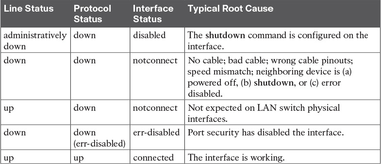
Table 1: LAN Switch Interface Status Codes
Examining the notconnect state for a moment, note that this state has many causes that have been mentioned through this section.
As you can see in the table, having a bad cable is just one of many reasons for the down/down state (or notconnect, per the show interfaces status command).
Some examples of the root causes of cabling problems include the following:
- The installation of any equipment that uses electricity, even non-IT equipment, can interfere with the transmission on the cabling, and make the link fail.
- The cable could be damaged, for example, if it lies under carpet. If the user’s chair keeps squashing the cable, eventually the electrical signal can degrade.
- Although optical cables do not suffer from electromagnetic interference (EMI), someone can try to be helpful and move a fiber-optic cable out of the way—bending it too much. A bend into too tight a shape can prevent the cable from transmitting bits (called macrobending).
For the other interface states listed in Table 1, only the up/up (connected) state needs more discussion. An interface can be in a working state, and it might really be working—or it might be working in a degraded state.
The next few topics discuss how to examine an up/up (connected) interface to find out whether it is working well or having problems.
Interface Speed and Duplex Issues
Many unshielded twisted-pair (UTP)-based Ethernet interfaces support multiple speeds, either full or half duplex, and support IEEE standard autonegotiation.
These same interfaces can also be configured to use a specific speed using the speed {10 | 100 | 1000} interface subcommand, and a specific duplex using the duplex {half | full} interface subcommand.
With both configured, a switch or router disables the IEEE-standard autonegotiation process on that interface.
The show interfaces and show interfaces status commands list both the actual speed and duplex settings on an interface, as demonstrated in Example 1.
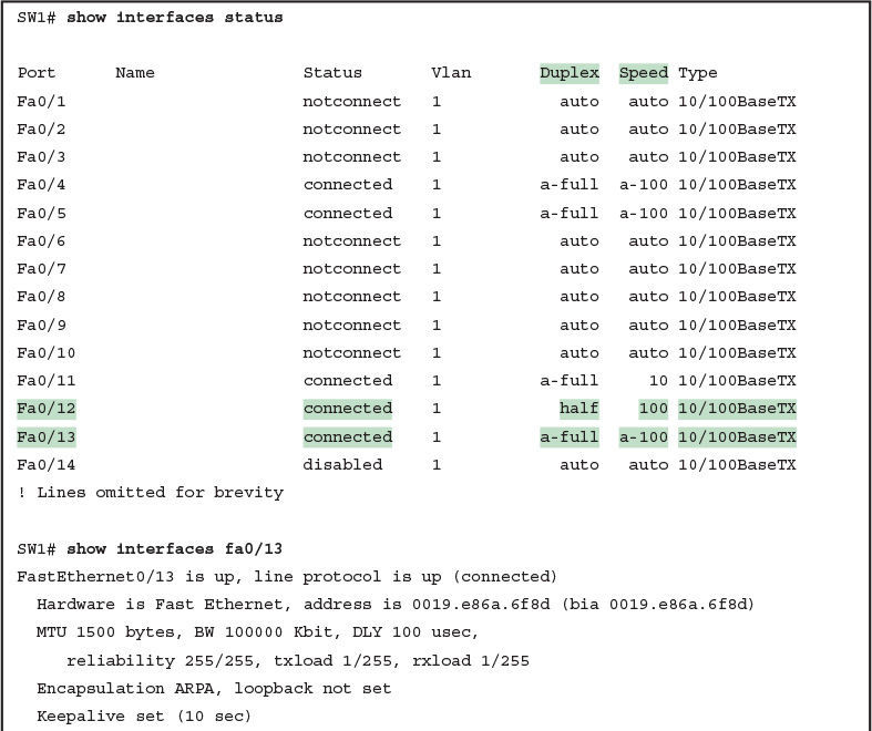
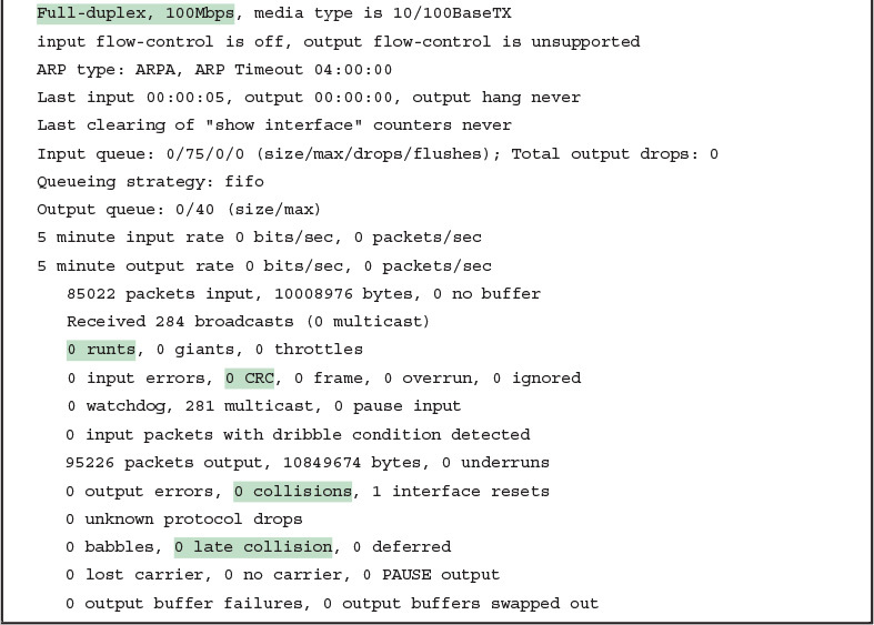
Example 1: Displaying Speed and Duplex Settings on Switch Interfaces
Although both commands in the example can be useful, only the show interfaces status command implies how the switch determined the speed and duplex settings. The command output lists autonegotiated settings with a prefix of a-.
For example, a-full means full duplex as autonegotiated, whereas full means full duplex but as manually configured. The example shades the command output that implies that the switch’s Fa0/12 interface’s speed and duplex were not found through autonegotiation, but Fa0/13 did use autonegotiation.
Note that the show interfaces fa0/13 command (without the status option) simply lists the speed and duplex for interface Fast Ethernet 0/13, with nothing implying that the values were learned through autonegotiation.
When the IEEE autonegotiation process works on both devices, both devices agree to the fastest speed supported by both devices. In addition, the devices use full duplex if it is supported by both devices, or half duplex if it is not. However, when one device has disabled autonegotiation, and the other device uses autonegotiation, the device using autonegotiation chooses the default duplex setting based on the current speed.
The defaults are as follows:
- If the speed is not known through any means, use 10 Mbps, half duplex.
- If the switch successfully senses the speed without IEEE autonegotiation, by just looking at the signal on the cable:
- If the speed is 10 or 100 Mbps, default to use half duplex.
- If the speed is 1,000 Mbps, default to use full duplex.
NOTE: Ethernet interfaces using speeds faster than 1 Gbps always use full duplex.
While autonegotiation works well, these defaults allow for the possibility of a difficult-to-troubleshoot problem called a duplex mismatch.
The “Autonegotiation” section in previous lesson explains how both devices could use the same speed, so the devices would consider the link to be up, but one side would use half-duplex and the other side would use full duplex.
The next example shows a specific case that causes a duplex mismatch.
In Figure 3, imagine that SW2’s Gi0/2 interface was configured with the speed 100 and duplex full commands (these settings are not recommended on a Gigabit-capable interface, by the way).
On Cisco switches, configuring both the speed and duplex commands disables IEEE autonegotiation on that port. If SW1’s Gi0/1 interface tries to use autonegotiation, SW1 would also use a speed of 100 Mbps, but default to use half duplex. Example 2 shows the results of this specific case on SW1.

Figure 3: Conditions to Create a Duplex Mismatch Between SW1 and SW2

Example 2: Confirming Duplex Mismatch on Switch SW1
First, focusing on the command output, the command confirms SW1’s speed and duplex. It also lists a prefix of a- in the output, implying autonegotiation. Even with SW1 using autonegotiation defaults, the command still notes the values as being learned through autonegotiation.
Finding a duplex mismatch can be much more difficult than finding a speed mismatch, because if the duplex settings do not match on the ends of an Ethernet segment, the switch interface will still be in a connected (up/up) state. In this case, the interface works, but it might work poorly, with poor performance, and with symptoms of intermittent problems.
The reason is that the device using half-duplex uses carrier sense multiple access collision detect (CSMA/CD) logic, waiting to send when receiving a frame, believing collisions occur when they physically do not—and actually stopping sending a frame because the switch thinks a collision occurred. With enough traffic load, the interface could be in a connect state, but it’s extremely inefficient for passing traffic.
To identify duplex mismatch problems, check the duplex setting on each end of the link and watch for incrementing collision and late collision counters, as explained in the next section.
Common Layer 1 Problems on Working Interfaces
When the interface reaches the connect (up/up) state, the switch considers the interface to be working. The switch, of course, tries to use the interface, and at the same time, the switch keeps various interface counters.
These interface counters can help identify problems that can occur even though the interface is in a connect state. This section explains some of the related concepts and a few of the most common problems.
Whenever the physical transmission has problems, the receiving device might receive a frame whose bits have changed values.
These frames do not pass the error detection logic as implemented in the FCS field in the Ethernet trailer.
The receiving device discards the frame and counts it as some kind of input error. Cisco switches list this error as a CRC error, as highlighted in Example 3. (Cyclic redundancy check [CRC] is a term related to how the frame check sequence [FCS] math detects an error.)

Example 3: Interface Counters for Layer 1 Problems
The number of input errors, and the number of CRC errors, are just a few of the counters in the output of the show interfaces command. The challenge is to decide which counters you need to think about, which ones show that a problem is happening, and which ones are normal and of no concern.
The example highlights several of the counters as examples so that you can start to understand which ones point to problems and which ones are just counting normal events that are not problems. The following list shows a short description of each highlighted counter, in the order shown in the example:
- Runts: Frames that did not meet the minimum frame size requirement (64 bytes, including the 18-byte destination MAC, source MAC, type, and FCS). Can be caused by collisions.
- Giants: Frames that exceed the maximum frame size requirement (1518 bytes, including the 18-byte destination MAC, source MAC, type, and FCS).
- Input Errors: A total of many counters, including runts, giants, no buffer, CRC, frame, overrun, and ignored counts.
- CRC: Received frames that did not pass the FCS math; can be caused by collisions.
- Frame: Received frames that have an illegal format, for example, ending with a partial byte; can be caused by collisions.
- Packets Output: Total number of packets (frames) forwarded out the interface.
- Output Errors: Total number of packets (frames) that the switch port tried to transmit, but for which some problem occurred.
- Collisions: Counter of all collisions that occur when the interface is transmitting a frame.
- Late Collisions: The subset of all collisions that happen after the 64th byte of the frame has been transmitted. (In a properly working Ethernet LAN, collisions should occur within the first 64 bytes; late collisions today often point to a duplex mismatch.)
Note that many of these counters occur as part of the CSMA/CD process used when half duplex is enabled. Collisions occur as a normal part of the half-duplex logic imposed by CSMA/CD, so a switch interface with an increasing collisions counter might not even have a problem.
However, one problem, called late collisions, points to the classic duplex mismatch problem.
If a LAN design follows cabling guidelines, all collisions should occur by the end of the 64th byte of any frame. When a switch has already sent 64 bytes of a frame, and the switch receives a frame on that same interface, the switch senses a collision.
In this case, the collision is a late collision, and the switch increments the late collision counter in addition to the usual CSMA/CD actions to send a jam signal, wait a random time, and try again.
With a duplex mismatch, like the mismatch between SW1 and SW2 in Figure 3, the half-duplex interface will likely see the late collisions counter increment.
Why? The half-duplex interface sends a frame (SW1), but the full duplex neighbor (SW2) sends at any time, even after the 64th byte of the frame sent by the half-duplex switch.
So, just keep repeating the show interfaces command, and if you see the late collisions counter incrementing on a half-duplex interface, you might have a duplex mismatch problem.
A working interface (in an up/up state) can still suffer from issues related to the physical cabling as well. The cabling problems might not be bad enough to cause a complete failure, but the transmission failures result in some frames failing to pass successfully over the cable.
For example, excessive interference on the cable can cause the various input error counters to keep growing larger, especially the CRC counter. In particular, if the CRC errors grow, but the collisions counters do not, the problem might simply be interference on the cable. (The switch counts each collided frame as one form of input error as well.)
Predicting Where Switches Will Forward Frames
Predicting the Contents of the MAC Address Table
Switches learn MAC addresses and then use the entries in the MAC address table to make a forwarding/filtering decision for each frame.
To know exactly how a particular switch will forward an Ethernet frame, you need to examine the MAC address table on a Cisco switch.
The more formal troubleshooting process begins with a mental process where you predict where frames should flow in the LAN. As an exercise, review Figure 4 and try to create a MAC address table on paper for each switch. Include the MAC addresses for both PCs, as well as the Gi0/1 MAC address for R1. (Assume that all three are assigned to VLAN 10.) Then predict which interfaces would be used to forward a frame sent by Fred, Barney, and R1 to every other device.

Sample Network Used in Switch MAC Learning Examples
The MAC table entries you predict in this case define where you think frames will flow. Even though this sample network in Figure 4 shows only one physical path through the Ethernet LAN, the exercise should be worthwhile, because it forces you to correlate what you’d expect to see in the MAC address table with how the switches forward frames. Figure 5 shows the resulting MAC table entries for PCs Fred and Barney, as well as for Router R1.
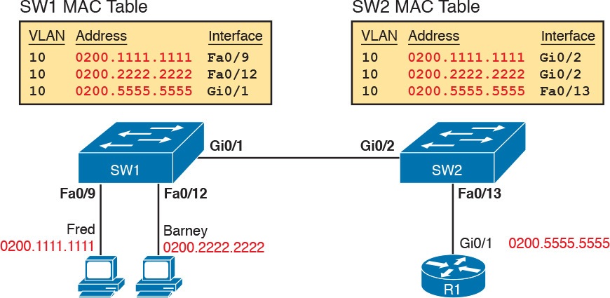
Predictions for MAC Table Entries on SW1 and SW2
While Figure 5 shows the concepts, Example 4 lists the same facts but in the form of the show mac address-table dynamic command on the switches. This command lists all dynamically learned MAC table entries on a switch, for all VLANs.
Example 4 Examining SW1 and SW2 Dynamic MAC Address Table Entries
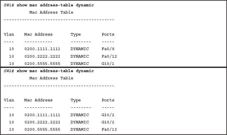
Examining SW1 and SW2 Dynamic MAC Address Table Entries
When predicting the MAC address table entries, you need to imagine a frame sent by a device to another device on the other side of the LAN and then determine which switch ports the frame would enter as it passes through the LAN. For example, if Barney sends a frame to Router R1, the frame would enter SW1’s Fa0/12 interface, so SW1 has a MAC table entry that lists Barney’s 0200.2222.2222 MAC address with Fa0/12. SW1 would forward Barney’s frame to SW2, arriving on SW2’s Gi0/2 interface, so SW2’s MAC table lists Barney’s MAC address (0200.2222.2222) with interface Gi0/2.
After you predict the expected contents of the MAC address tables, you can then examine what is actually happening on the switches, as described in the next section.
Analyzing the Forwarding Path
Troubleshooting revolves around three big ideas: predicting what should happen, determining what is happening that is different than what should happen, and figuring out why that different behavior is happening. This next section discusses how to look at what is actually happening in a VLAN based on those MAC address tables, first using a summary of switch forwarding logic and then showing an example.
The following list summarizes switch forwarding logic including the LAN switching features discussed in this study:
Step 1. Process functions on the incoming interface, if the interface is currently in an up/up (connected) state, as follows:
A. If configured, apply port security logic to filter the frame as appropriate.
B. If the port is an access port, determine the interface’s access VLAN.
C. If the port is a trunk, determine the frame’s tagged VLAN.
Step 2. Make a forwarding decision. Look for the frame’s destination MAC address in the MAC address table, but only for entries in the VLAN identified in Step 1. If the destination MAC is...
A. Found (unicast), forward the frame out the only interface listed in the matched address table entry.
B. Not found (unicast), flood the frame out all other access ports (except the incoming port) in that same VLAN, plus out trunks that have not restricted the VLAN from that trunk.
C. Broadcast, flood the frame, with the same rules as the previous step.
For an example of this process, consider a frame sent by Barney to its default gateway, R1 (0200.5555.5555). Using the steps just listed, the following occurs:
Step 1. Input interface processing:
A. The port does not happen to have port security enabled.
B. SW1 receives the frame on its Fa0/12 interface, an access port in VLAN 10.
Step 2. Make a forwarding decision: SW1 looks in its MAC address table for entries in VLAN 10:
A. SW1 finds an entry (known unicast) for 0200.5555.5555, associated with VLAN 10, outgoing interface Gi0/1, so SW1 forwards the frame only out interface Gi0/1. (This link is a VLAN trunk, so SW1 adds a VLAN 10 tag to the 802.1Q trunking header.)
At this point, the frame with source 0200.2222.2222 (Barney) and destination 0200.5555.5555 (R1) is on its way to SW2. You can then apply the same logic for SW2, as follows:
Step 1. Input interface processing:
A. The port does not happen to have port security enabled.
B. SW2 receives the frame on its Gi0/2 interface, a trunk; the frame lists a tag of VLAN 10. (SW2 will remove the 802.1Q header as well.)
Step 2. Make a forwarding decision: SW2 looks for its MAC table for entries in VLAN 10:
A. SW2 finds an entry (known unicast) for 0200.5555.5555, associated with VLAN 10, outgoing interface Fa0/13, so SW2 forwards the frame only out interface Fa0/13.
At this point, the frame should be on its way, over the Ethernet cable between SW2 and R1.
Analyzing Port Security Operations on an Interface
Generally speaking, any analysis of the forwarding process should consider any security features that might discard some frames or packets. For example, both routers and switches can be configured with access control lists (ACL) that examine the packets and frames being sent or received on an interface, with the router or switch discarding those packets/frames.
This study does not include coverage of switch ACLs, but the exams do cover a switch feature called port security. Port security feature can be used to cause the switch to discard some frames sent into and out of an interface. Port security has three basic features with which it determines which frames to filter:
Limit which specific MAC addresses can send and receive frames on a switch interface, discarding frames to/from other MAC addresses
Limit the number of MAC addresses using the interface, discarding frames to/from MAC addresses learned after the maximum limit is reached
A combination of the previous two points
The first port security troubleshooting step should be to find which interfaces have port security enabled, followed by a determination as to whether any violations are currently occurring. The trickiest part relates to the differences in what the IOS does in reaction to violations based on the switchport port-security violation violation-mode interface subcommand, which tells the switch what to do when a violation occurs. The general process to find port security issues is as follows:
Step 1. Identify all interfaces on which port security is enabled (show running-config or show port-security).
Step 2. Determine whether a security violation is currently occurring based in part on the violation mode of the interface’s port security configuration, as follows:
A. shutdown: The interface will be in an err-disabled state, and the port security port status will be secure-down.
B. restrict: The interface will be in a connected state, the port security port status will be secure-up, but the show port-security interface command will show an incrementing violations counter.
C. protect: The interface will be in a connected state, and the show port-security interface command will not show an incrementing violations counter.
Step 3. In all cases, compare the port security configuration to the diagram and to the Last Source Address field in the output of the show port-security interface command.
Because IOS reacts so differently with shutdown mode as compared to restrict and protect modes, the next few pages explain the differences—first for shutdown mode, then for the other two modes.
Troubleshooting Shutdown Mode and Err-disabled Recovery
Troubleshooting Step 2A refers to the interface err-disabled (error-disabled) state. This state verifies that the interface has been configured to use port security, that a violation has occurred, and that no traffic is allowed on the interface at the present time. This interface state implies that the shutdown violation mode is used, because it is the only one of the three port security modes that causes the interface to be disabled.
To recover from an err-disabled state, the interface must be shut down with the shutdown command, and then enabled with the no shutdown command. Example 5 lists an example in which the interface is in an err-disabled state.
Example 5 Using Port Security to Define Correct MAC Addresses of Particular Interfaces
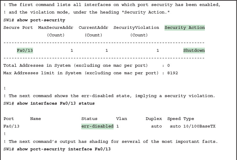
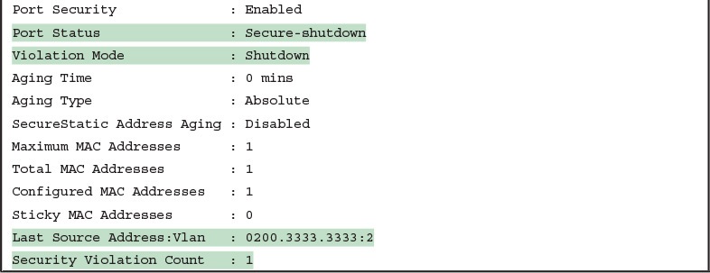
The output of the show port-security interface command lists a couple of items helpful in the troubleshooting process. The port status of secure-shutdown means that the interface is disabled for all traffic as a result of a violation while in port security shutdown mode; this state is not used by the protect and restrict modes. The port security port status of secure-shutdown also means that the interface state should be err-disabled.
Note that in shutdown mode, the violations counter (at the bottom of the output) does not keep incrementing. Basically, once the first violating frame triggers IOS to move the port to an err-disabled state, IOS ignores any other incoming frames (not even counting them) until the engineer uses the shutdown and no shutdown commands on the interface, in succession. Note that the process of recovering the interface also resets the violation counter back to 0. Finally, note that the second-to-last line lists the source MAC address of the last frame received on the interface. This value can prove useful in identifying the MAC address of the device that caused the violation.
Figure 6 summarizes these behaviors, assuming the same scenario shown in the example.
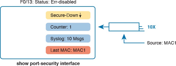
Summary of Actions: Port Security Violation Mode Shutdown
Troubleshooting Restrict and Protect Modes
The restrict and protect violation modes take a much different approach to securing ports. These modes still discard offending traffic, but the interface remains in a connected (up/up) state, and in a port security state of secure-up. As a result, the port continues to forward good traffic and discard offending traffic.
Having a port in a seemingly good state that also discards traffic can be a challenge when troubleshooting. Basically, you have to know about this possible pitfall, and then know how to tell when port security is discarding some traffic on a port even though the interface status looks good.
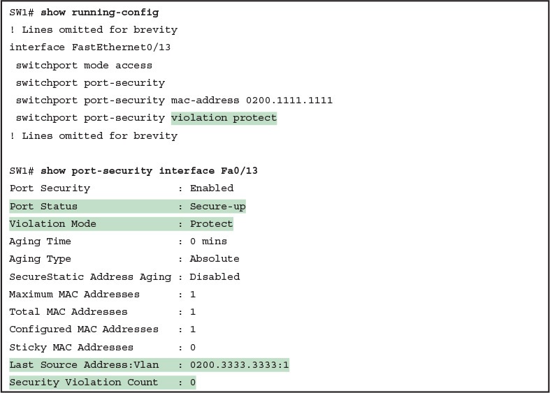
The show port-security interface command reveals whether protect mode has discarded frames using the “last source address” item in the output. Example 6 shows a sample configuration and show command when using protect mode. In this case, the port is configured to allow Fa0/13 to receive frames sent by 0200.1111.1111 only. Ten frames have arrived, with a variety of source MAC addresses, with the last frame’s source MAC address being 0200.3333.3333.
Example 6 Port Security Using Protect Mode
Port Security Using Protect Mode
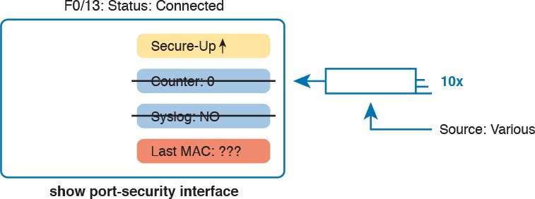
In protect mode, the show port-security interface command reveals practically nothing about whether the interfaces happen to be discarding traffic or not. For instance, in this case, this show command output was gathered after many frames had been sent by a PC with MAC address 0200.3333.3333, with all the frames being discarded by the switch because of port security. The command output shows the disallowed PC’s 0200.3333.3333 MAC address as the last source MAC address in a received frame. However, if another frame with an allowed MAC address arrived (in this case, source MAC 0200.1111.1111), the next instance of the show command would list 0200.1111.1111 as the last source address. In particular, note that the interface remains in a secure-up state, and the violation counter does not increment.
Figure 7 summarizes the key points about the operation of Port Security protect mode, assuming a mix of frames with different source addresses. The figure emphasizes unpredictability of the last source MAC listed in the output, and the fact that the counter does not increment and that no syslog messages are generated for violating frames.
Summary of Actions: Port Security Violation Mode Protect
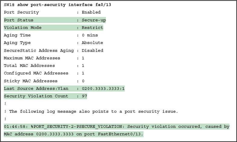
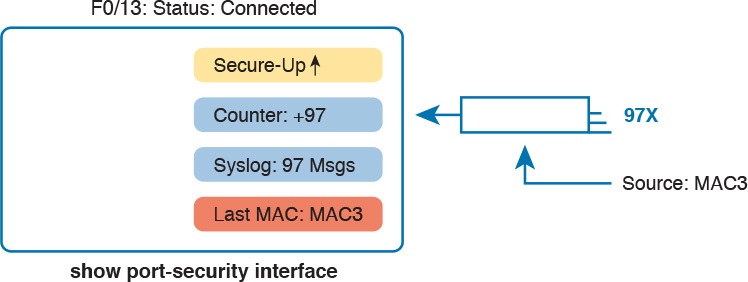
If this example had used violation mode restrict instead of protect, the port status would have also remained in a secure-up state; however, IOS would show some indication of port security activity, such as the incrementing violation counter as well as syslog messages. Example 7 shows an example of the violation counter and ends with an example port security syslog message. In this case, 97 incoming frames so far violated the rules, with the most recent frame having a source MAC address of 0200.3333.3333.
Example 7 Port Security Using Violation Mode Restrict
Port Security Using Violation Mode Restrict
Figure 8 summarizes the key points about the restrict mode for port security. In this case, the figure matches the same scenario as the example again, with 97 total violating frames arriving so far, with the most recent being from source MAC MAC3.
Summary of Actions: Port Security Violation Mode Restrict
For the exams, a port security violation might not be a problem; it might be the exact function intended. The question text might well explicitly state what port security should be doing. In these cases, it can be quicker to just immediately look at the port security configuration. Then, compare the configuration to the MAC addresses of the devices connected to the interface. The most likely problem on the exams is that the MAC addresses have been misconfigured or that the maximum number of MAC addresses has been set too low.
Analyzing VLANs and VLAN Trunks
A switch’s forwarding process, as discussed earlier in the section “Analyzing the Forwarding Path,” depends in part on VLANs and VLAN trunking. Before a switch can forward frames in a particular VLAN, the switch must know about a VLAN and the VLAN must be active. And before a switch can forward a frame over a VLAN trunk, the trunk must currently allow that VLAN to pass over the trunk. This final of the five major sections in this lesson focuses on VLAN and VLAN trunking issues, specifically issues that impact the frame switching process. The four potential issues are as follows:
Step 1. Identify all access interfaces and their assigned access VLANs and reassign into the correct VLANs as needed.
Step 2. Determine whether the VLANs both exist (configured or learned with VTP) and are active on each switch. If not, configure and activate the VLANs to resolve problems as needed.
Step 3. Check the allowed VLAN lists, on the switches on both ends of the trunk, and ensure that the lists of allowed VLANs are the same.
Step 4. Check for incorrect configuration settings that result in one switch operating as a trunk, with the neighboring switch not operating as a trunk.
Ensuring That the Right Access Interfaces Are in the Right VLANs
To ensure that each access interface has been assigned to the correct VLAN, engineers simply need to determine which switch interfaces are access interfaces instead of trunk interfaces, determine the assigned access VLANs on each interface, and compare the information to the documentation. The show commands listed in Table 2 can be particularly helpful in this process.

Commands That Can Find Access Ports and VLANs
If possible, start this step with the show vlan and show vlan brief commands, because they list all the known VLANs and the access interfaces assigned to each VLAN. Be aware, however, that these two commands do not list operational trunks. The output does list all other interfaces (those not currently trunking), no matter whether the interface is in a working or nonworking state.
If the show vlan and show interface switchport commands are not available in a particular exam question, the show mac address-table command can also help identify the access VLAN. This command lists the MAC address table, with each entry including a MAC address, interface, and VLAN ID. If the exam question implies that a switch interface connects to a single device PC, you should only see one MAC table entry that lists that particular access interface; the VLAN ID listed for that same entry identifies the access VLAN. (You cannot make such assumptions for trunking interfaces.)
After you determine the access interfaces and associated VLANs, if the interface is assigned to the wrong VLAN, use the switchport access vlan vlan-id interface subcommand to assign the correct VLAN ID.
Access VLANs Not Being Defined
Switches do not forward frames for VLANs that are (a) not configured or (b) configured but disabled (shut down). This section summarizes the best ways to confirm that a switch knows that a particular VLAN exists, and if it exists, determines the state of the VLAN.
First, on the issue of whether a VLAN is defined, a VLAN can be defined to a switch in two ways: using the vlan number global configuration command, or it can be learned from another switch using VTP. This study purposefully ignores VTP as much as possible, so for this discussion, consider that the only way for a switch to know about a VLAN is to have a vlan command configured on the local switch.
Next, the show vlan command always lists all VLANs known to the switch, but the show running-config command does not. Switches configured as VTP servers and clients do not list the vlan commands in the running-config nor the startup-config file; on these switches, you must use the show vlan command. Switches configured to use VTP transparent mode, or that disable VTP, list the vlan configuration commands in the configuration files. (Use the show vtp status command to learn the current VTP mode of a switch.)
After you determine that a VLAN does not exist, the problem might be that the VLAN simply needs to be defined.
Access VLANs Being Disabled
For any existing VLANs, also verify whether the VLAN is active. The show vlan command should list one of two VLAN state values, depending on the current state: either active or act/lshut. The second of these states means that the VLAN is shut down. Shutting down a VLAN disables the VLAN on that switch only, so that the switch will not forward frames in that VLAN.
Switch IOS gives you two similar configuration methods with which to disable (shutdown) and enable (no shutdown) a VLAN. Example 8 shows how, first by using the global command [no] shutdown vlan number and then using the VLAN mode subcommand [no] shutdown. The example shows the global commands enabling and disabling VLANs 10 and 20, respectively, and using VLAN subcommands to enable and disable VLANs 30 and 40 (respectively).
Example 8 Enabling and Disabling VLANs on a Switch
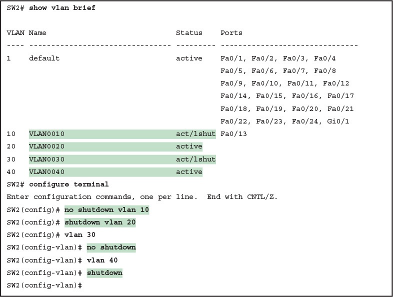
Enabling and Disabling VLANs on a Switch
Mismatched Trunking Operational States
Trunking can be configured correctly so that both switches forward frames for the same set of VLANs. However, trunks can also be misconfigured, with a couple of different results. In some cases, both switches conclude that their interfaces do not trunk. In other cases, one switch believes that its interface is correctly trunking, while the other switch does not.
The most common incorrect configuration—which results in both switches not trunking—is a configuration that uses the switchport mode dynamic auto command on both switches on the link. The word “auto” just makes us all want to think that the link would trunk automatically, but this command is both automatic and passive. As a result, both switches passively wait on the other device on the link to begin negotiations.
With this particular incorrect configuration, the show interfaces switchport command on both switches confirms both the administrative state (auto), as well as the fact that both switches operate as “static access” ports. Example 9 highlights those parts of the output from this command.
Example 9 Operational Trunking State

Operational Trunking State
A different incorrect trunking configuration results in one switch with an operational state of “trunk,” while the other switch has an operational state of “static access.” When this combination of events happens, the interface works a little. The status on each end will be up/up or connected. Traffic in the native VLAN will actually cross the link successfully. However, traffic in all the rest of the VLANs will not cross the link.
Figure 9 shows the incorrect configuration along with which side trunks and which does not. The side that trunks (SW1 in this case) enables trunking always, using the command switchport mode trunk. However, this command does not disable DTP negotiations. To cause this particular problem, SW1 also disables DTP negotiation using the switchport nonegotiate command. SW2’s configuration also helps create the problem, by using a trunking option that relies on DTP. Because SW1 has disabled DTP, SW2’s DTP negotiations fail, and SW2 does not trunk.

Mismatched Trunking Operational States
In this case, SW1 treats its G0/1 interface as a trunk, and SW2 treats its G0/2 interface as an access port (not a trunk). As shown in the figure at Step 1, SW1 could (for example) forward a frame in VLAN 10 (Step 1). However, SW2 would view any frame that arrives with an 802.1Q header as illegal, because SW2 treats its G0/2 port as an access port. So, SW2 discards any 802.1Q frames received on that port.
To deal with the possibility of this problem, always check the trunk’s operational state on both sides of the trunk. The best commands to check trunking-related facts are show interfaces trunk and show interfaces switchport.
NOTE: Frankly, in real life, just avoid this kind of configuration. However, the switches do not prevent you from making these types of mistakes, so you need to be ready.
